
2012 Yamaha R6 Full Engine Rebuild: Part 4, Reassembly
Recap: I rebuilt a 2012 R6 motor for a bike that I use as a track bike. Due to high mileage (>30k), poor low end performance, and compression much lower than spec, (as well as my “mechanical enthusiasm”) I decided to go ahead and do a full rebuild of the engine as well as a general cleanup of the chassis and cabling. This article is Part 4: Reassembly, and deals with component acquisition, engine re-assembly, and finally startup and break-in.
This is one article in a series, which will detail the rebuild as well as offer guidance to any aspiring mechanics:
- Part 1, Introduction: Motivation, how to get started, and critical chemicals and tooling.
- Part 2, Disassembly: Some key parts of disassembly not well covered in the manual/other sources.
- Part 3, Inspection & Cleaning: Combustion chamber surfaces, valve and piston installation, valve clearance adjustment.
- Part 4, Reassembly: Some key parts of assembly not well covered in the manual/other sources. Starting it up and break-in period.
With this series of articles I aim to offer technical advice that is not well covered elsewhere, and concentrate it all in one resource. This series specifically focuses on the Yamaha R6, but will generally apply to any modern inline-4 supersport (600cc) or superbike (1000cc) motor (very similar construction between modern, fuel-injected, water-cooled aluminium racing engines).
1 General Guidance
The following should be done at every step of the re-assembly process:
- Engine oil on every torqued fastener. You may want to use anti seize compound on external fasteners, but for internal fasteners the oil is fine.
- Lithium soap grease on every rubber gasket.
- Consider cleaning out all threaded holes with the respective tap. At minimum any small (M6) threaded holes that need to be torqued should be cleaned in this way.
- Assembly lube, or equivalent on all shaft journals. For this I used a 1:1 Yamalube molybdenum disulfide grease to engine oil mixture, this is the “molybdenum-disulfide oil” specified in the manual.
- Mating surfaces should undergo a final clean with brake cleaner and a lint-free wipe.
In general, engine oil is your friend. Lube all that stuff up!
2 Ordering Components
I’ve uploaded my Partzilla BOM for viewing. It’s pretty close to what you would find in most pre-compiled engine rebuild kits. However, it’s not exactly the same and I went through the parts pages individually to select what I thought was a necessary purchase. For example, I wanted to completely replace my cam chain tensioner guide (13S-12252-00-00) due to significant wear, and that item is not typically included in standard kits. If it’s a paper gasket or the head gasket, it needs to be replaced. I also replaced any Viton/rubber gasket and all copper crush washers. I do not suggest simply copying my BOM, as certain items, such as connecting rod/crankshaft journal bearings, will not be suitable for your particular bike.
Here are my comments on replacing certain other components:
- 94591-641188-00 (camshaft timing chain): These stretch over time, making excessive noise and requiring deeper tensioner application/force.
- 13S-12252-00-00 (timing chain tensioner guide): Mine was burned in places, indicating excessive chain pressure, and had large grooves in it. A new unmarred surface will reduce the pressure on it.
- 13S-11416-XX-00 (crankshaft journal bearing): These can be reused if you do the plastigauge test and find nominal clearance and no excessive wear. However, if your crank journal diameter is nominal (easier to measure than the case journal), it’s also trivial and cheap to replace them at $40/set. Please refer to the service manual on how to size these, the “XX” will be different based on the factory journal diameter measurements.
- 2C0-11654-00-00 (connecting rod bolt): These are stretch bolts and are not meant to be reused, it’s a mandatory replacement.
- 13S-11656-XX-00 (connecting rod bearing): I think this is a mandatory replacement as well due to the uneven wear you would expect on these compared to the crankshaft plane bearings. Please refer to the service manual on how to size these, the “XX” will be different based on the factory journal diameter measurements.
- 93306-20562-00, 93306-20464-00, 93305-20509-00(main/drive axle bearings): I did not replace mine as they looked pristine and rotated freely when oiled. At higher mileages this may be necessary to reduce noise and axle runout.
- 4SV-12119-00-00 (valve stem seal): If you want to avoid oil in your combustion chamber or gas in your oil, these will help you out, surely.
- 93102-35017-00 (drive axle oil seal): Ok, you can also re-use it and line the edge with RTV Silicone, but I replaced it.
It’s highly possible to get away with reusing every component, but reusing the connecting rod bolts, for example, is probably dangerous, and you should evalute the potential cost/likelyhood of component failure. Otherwise, I also recommend getting an aftermarket manual cam chain tensioner over the stock one, as you can eliminate the “dead zone” between tensioner notches at low oil pressure (low rpm) and reduce the noise greatly. I’ve also heard people recommend the replacement of the main bolts on the crankcase that line the crankshaft (there are 10 of them, 90119-08083-00), but I’ve also heard of mechanics reusing them. More importantly, the service manual indicates that the connecting rod bolts are a mandatory replacement, and says nothing of any crankcase bolt. My judgement was that they are a much larger size bolt than the connecting rod bolts and not likely to fail after repeated torqueing, so I reused them. Feel free to use critical thinking here, even if a professional race mechanic says otherwise: their cost/benefit judgement may be completely different than yours.
3 Cylinder Head and Valve Clearance
I started with rebuilding the cylinder head because I wanted to see the improvement in valve seal, and also get my new shims ordered. This valve system is a dual overhead cam (DOHC) shim-in-bucket system. This simply means that the spacing between the valve stem and cam lobe is set by a steel shim, ranging from 1.5 mm to over 2.5 mm (see Figure 1 (right)). Over time, the actual clearance changes due to component wear. Either the valve stem itself can wear and increase the gap (less likely with Ti valves), or the valve digs into the valve seat and the gap is reduced (more likely, higher mileage supersport engines tend to have “tighter valves”). For example, if you were to do a full head refurbishment and get the seats re-cut, this could close the gap below the minimum shim spec. In that situation, you would have to grind down the end of the valve stem to increase the gap past the minimum shim size, and then size a replacement shim appropriately. With my engine, I did a clearance measurement on disassembly and found five valves had no gap between cam lobe and bucket, meaning they never fully close (hence the leaking, at least some of it). To measure my clerances, I actually had to bend the feeler gauges as shown:
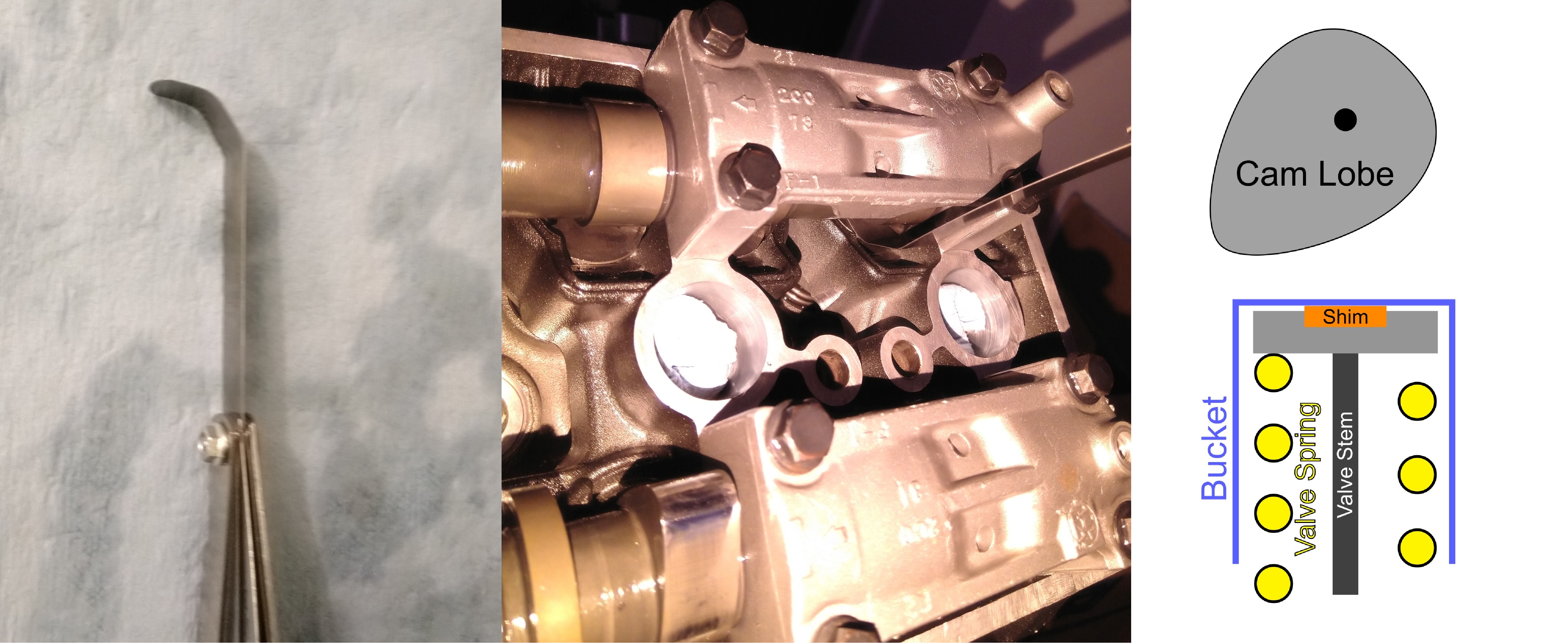
If I used the standard feeler gauge angle, they would seize between the cam lobe and cylinder head and prevent me from getting an accurate measurement. The spec gap between cam lobe and bucket is [0.12, 0.19] mm for intake valves and [0.16-0.23] mm for exhaust. I started by installing 1.55 mm shims, one size above the absolute minimum, in all of the valves and reinstalling the camshafts. I then measured the clerances and calculated the shim size required to hit right below the maximum spec clearance (e.g. 0.19 mm for intake) for each valve. The reason for this is that larger gaps simply result in slightly more noise but are guaranteed to fully close. After I installed the final shims, I did another leak test:
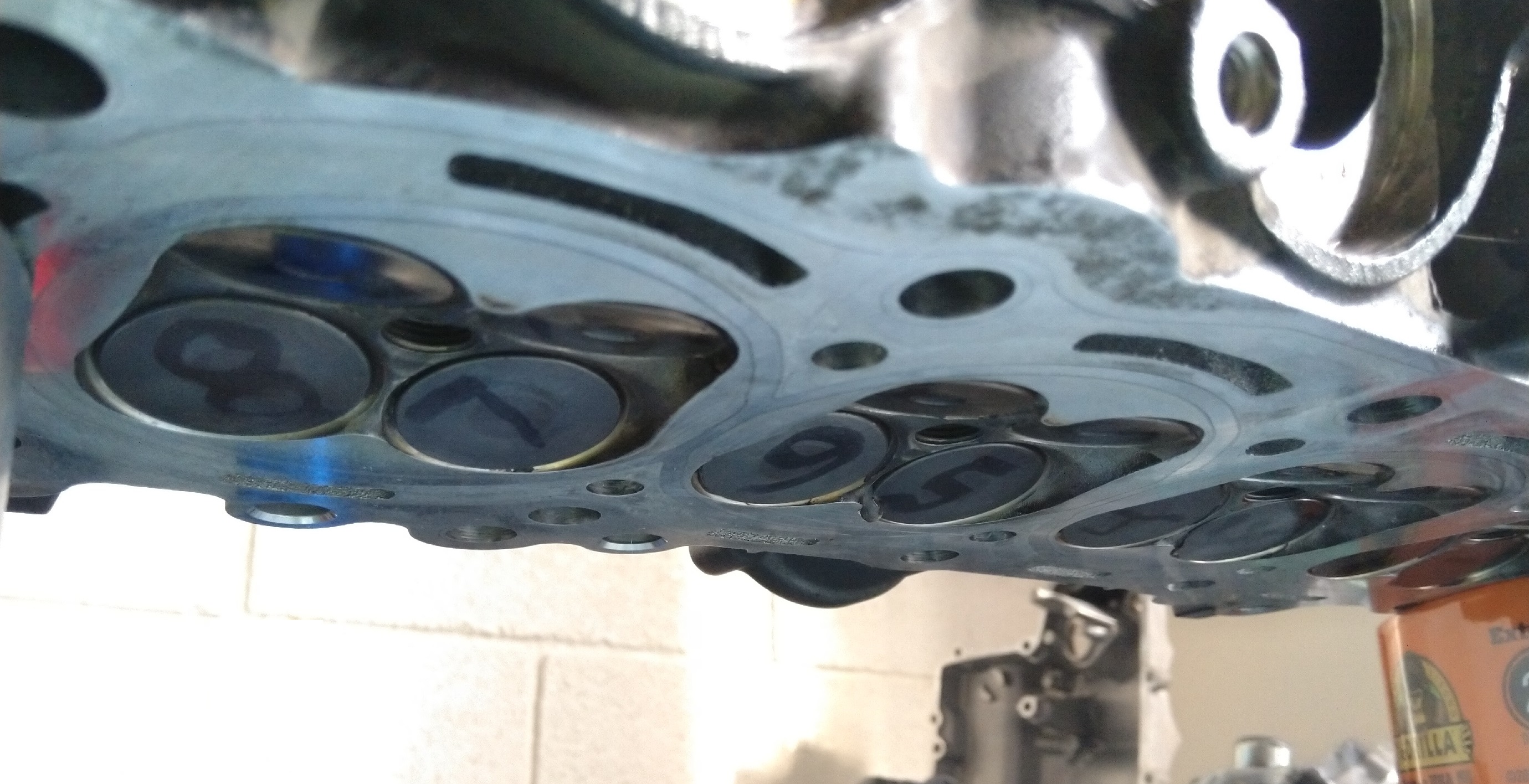
and noticed no leaking or beading for over 3 minutes! One of the exhaust valves starting beading water shortly after but that may just seal completely after running the engine. Additionally, exhaust valves are more substantially thermal cycled than intake and tend to warp out of spec faster. Regardless, this is an excellent result. I talked to a race mechanic about this and was told that even a few seconds of sealing is quite fine, as the seal will improve drastically under heat/load, so you don’t need to worry about small beads unless your valves are freely dripping water.
4 Pistons
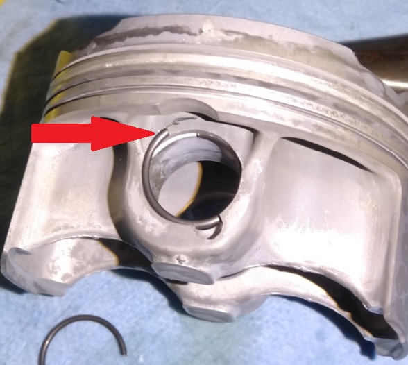
This was probably the most tricky installation item for me. Full disclosure: I bent two sets of oil spreader rings, so if you’ve never done this before, get ready to use an extra ring pack or two (the oil spreader and top/bottom rings come in a set, $30 each!). The first challenge here is installing the piston rod end clips, which I did by forcing one end into the groove, rotating them, and then just pushing hard with both thumbs on the end of the clip until it slid into the groove:
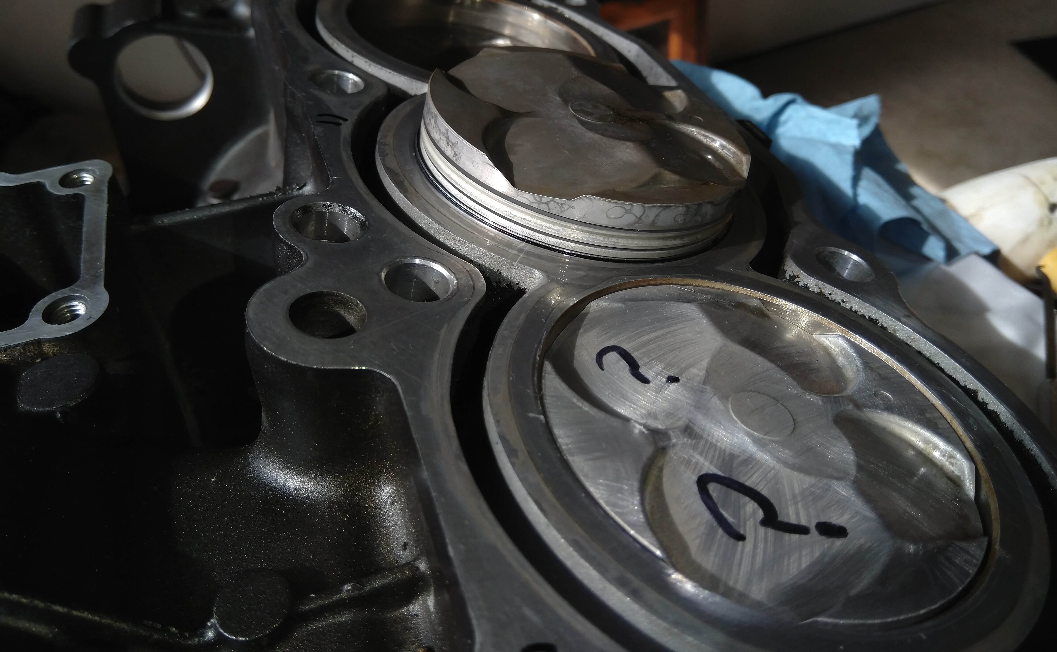
Then came the piston installation. For the very first piston, I used a store-bought ring compressor and excessively lubricated the compressor, cylinder and piston with engine oil. I then gently placed everything together and tapped the piston in (gently) with my rubber mallet. The first piston went in without problem, but the second piston suffered a bent oil spreader ring and went in a bit misaligned. I could tell something was funny as it was tilting a bit in the cylinder:
The top/bottom ring are basically indestructible, you would have to attack them with a tool or strain them beyond fracture to cause significant damage, but the spreader package may just be the most fragile item in the entire engine. I bent a second one before I realized it was catching in the gap in the store-bought adjustable ring compressor and tilting slightly before the piston left the compressor. This is a valuable lesson: adjustable piston ring compressors are garbage, don’t buy them. What you really want here is a tapered spec piston compressor/installer for your particular engine:
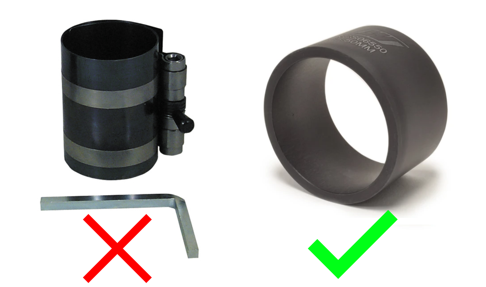
With the tapered installer, you can gently push the whole thing in with your finger. Look at this person, look at how smart they are (how easy is that???). I didn’t have these tapered installers on hand, so what I ended up doing was installing the spreader rings and gently coaxing the piston down straight. Then, using a ring expander I carefully positioned the bottom ring and pushed the piston in more. When the bottom ring is in the cylinder, the piston assembly is tight against the cylinder walls and does not move as much, making the top ring very easy to install. When the piston is installed and square, push it down until the connecting rod just sticks out of cylinder, and install the crankshaft, etc, as indicated in the manual. If you have to redo something and remove the piston, remember to not re-use the connecting rod bolts as they are stretch bolts.
5 Cam Timing Chain and Tensioner
I also recommend moving to a manual cam tensioner. This will sound much better than the stock tensioner at lower rpm ranges because it won’t float at low oil pressure. The caveat is increased wear of the tensioner arm, but that is why I bought a new one! This will have to be re-adjusted after the break-in cycle regardless, but for now it’s fine to just push the tensioner in until there is a firm pressure on the chain:
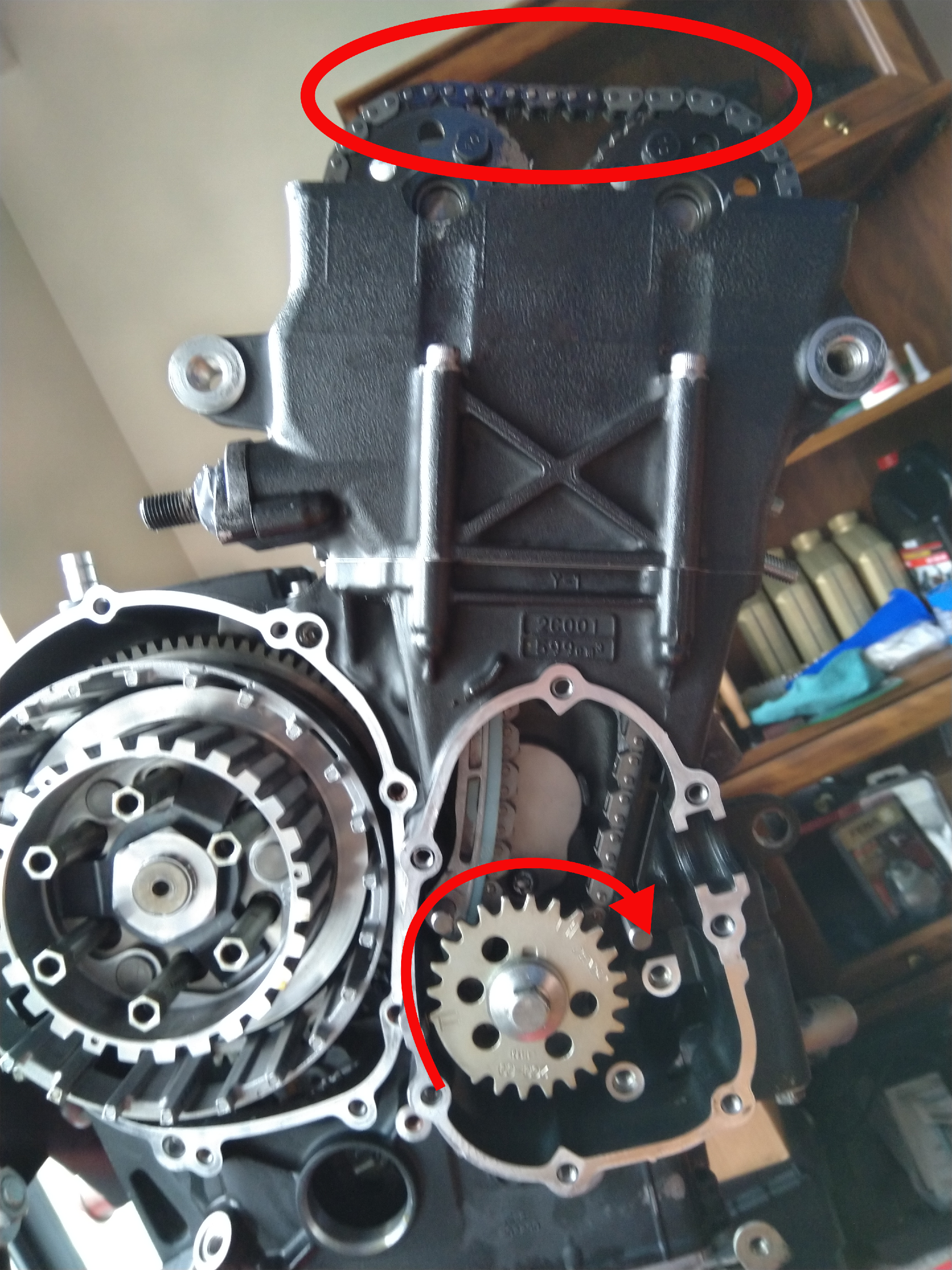
To get a baseline tension, slowly turn the engine over and watch the chain re-engage the exhaust cam sprocket. If the tensioner is too loose it will bulge upwards and bunch up before it engages the sprocket teeth. I simply increased the tension until the chain motion was smooth and locked it in with two jam nuts and some RTV silicone. When the break-in period is over, you can fine tune this to find the optimal balance between chain noise reduction and parasitic torque on the crankshaft. For this final adjustment, I start the engine and then I loosen the tensioner slightly (and carefully, no more than a few turns or you may lose cam timing and have a catastrophic failure) until I hear a dominant “clacking” sound. I then increase tension until I get a 50/50 mix between “clacking” and “whirring”. The “whirring” is like a belt sander sound that the chain makes when it rubs against the tensioner arm. Too much “whirring” means that the cam chain is too tight, and it’s likely that the bike won’t easily start.
6 Final Assembly
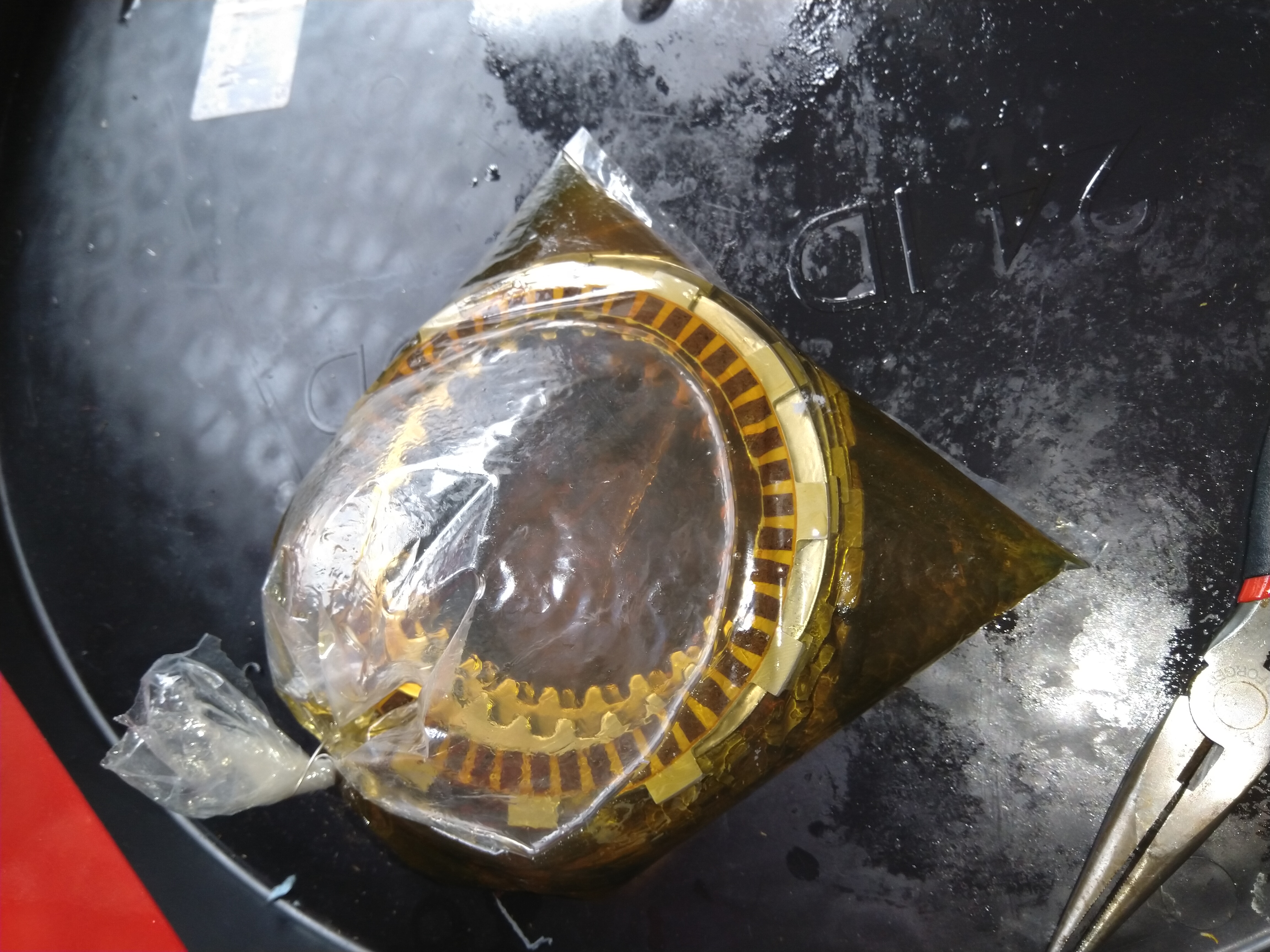
I recommend soaking the clutch plates for at least one hour in engine oil. If the friction pads are not soaked in oil and you start the engine, it’s possible they won’t disengage from the plates. This is mostly a concern if it has been sitting for a long time. I just left it in a bag for an hour:
I also highly recommend keeping all engine ports covered and taped over until final install:
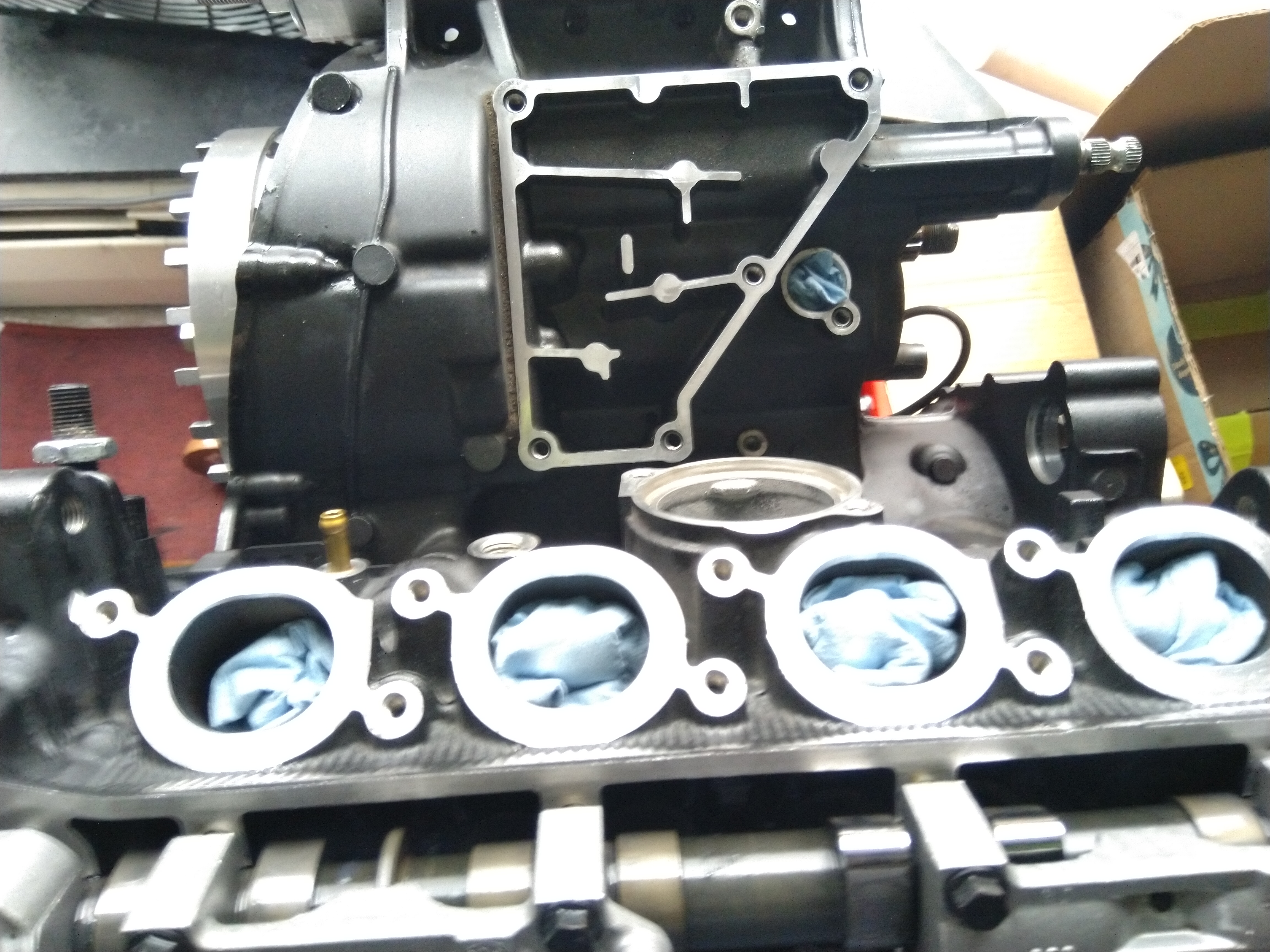
It was quite a learning process, but eventually the full engine was put back together:
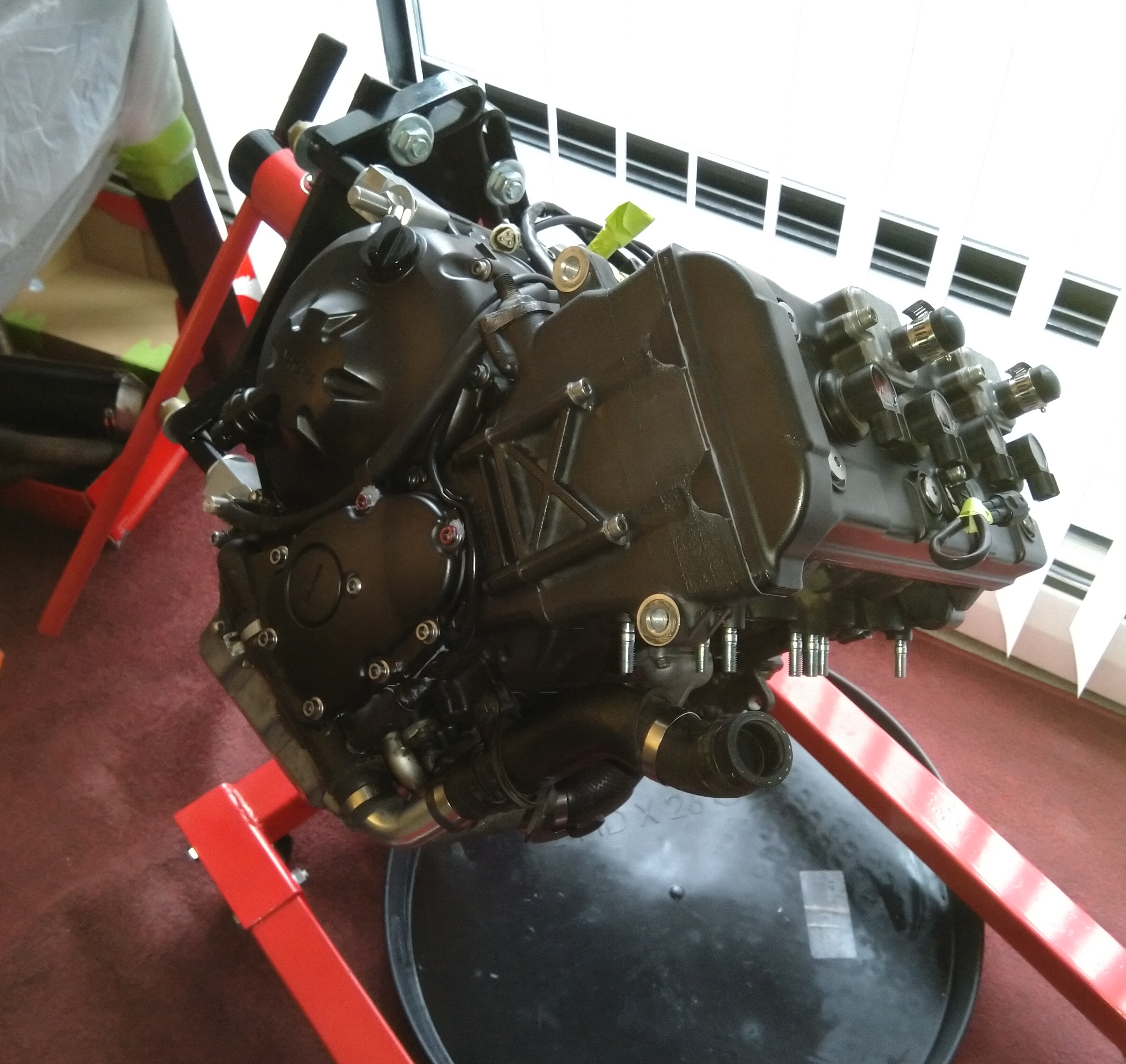
I removed the air induction system and sealed off that port by reversing the reed valves and hose clamping tubing over it. There are aftermarket cover plates but I forgot to order them and didn’t want to wait for them to arrive at this point (good enough for now…). Alright, let’s put it back in the bike and see if it runs!
7 Reinstallation
I mentioned this in the disassembly article, but I think it’s almost impossible to put this bike back together the wrong way. I simply kept all wiring harnesses and hoses out of the way of any engine maneuvering, and then carefully re-connected everything one by one:
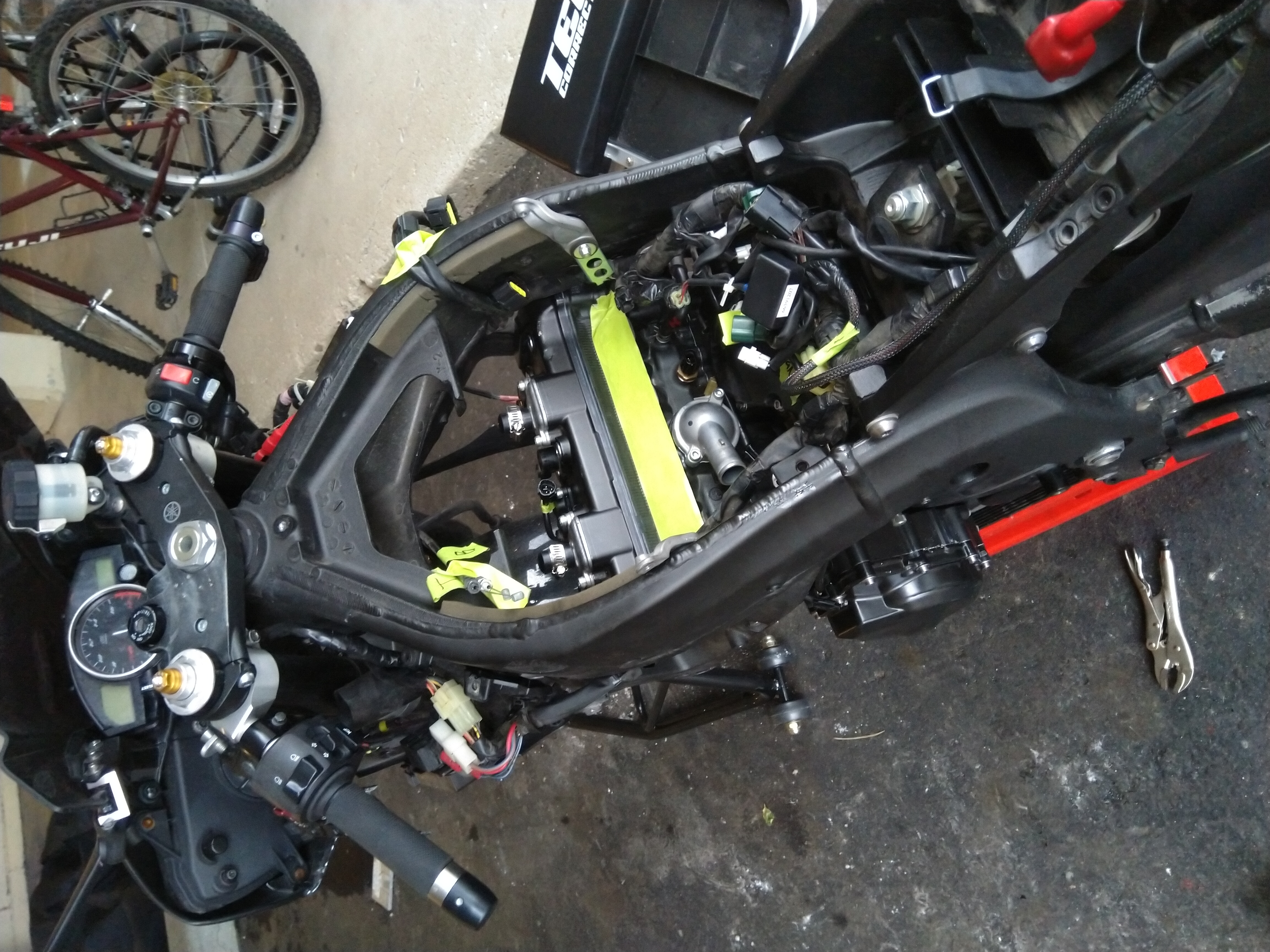
Due to the uniqueness of each cable/assembly, I found that I did not need to look at the manual for most of the reinstallation. Before the final pieces went on, I filled it up with 10W40 mineral oil (don’t use synthetic oil for break-in) and coolant. After what seems like 1000 years of tedious bodywork reinstallation (the stock plastics on most supersports from this era are quite poorly designed), I filled it with gas and turned it back on. You may have to hold the starter for a bit to ensure good oil distribution, but my bike went into warmup/idle just fine after pressing the starter normally. On the advice of my mechanic, I applied throttle to rev it up to 4-5k and distribute the oil right after startup, but I suspect this is not necessary. After ~ 10 minutes of the engine running, I shut it off and drained the oil. It is highly recommended to change the oil shortly after the first start as you have now distributed all of the assembly grease, etc, into the oil. Indeed, mine was a frothy darker color, compared to the usual amber.

As far as break-in goes, if I took away one thing from this project it is that modern metallurgy is space magic and that most of these components are borderline indestructible. If there is no damage to your cylinder plating, the rings will seat fine with the factory breakin. I’ve read that people break in race bikes by pulling to redline to ensure good ring seal. My thought here is that the initial startup should focus on oil distribution on critical surfaces, initial wearing, and the replacement of assembly lube. Afterwards, methodical pulls up to redline are probably fine. After that first oil change, I did some staggered pulls first to midrange (7-10k), and then up to 16.5k for short bursts. At 500 miles, I changed the filter and oil, and then continued with regularly scheduled maintainance items. On the track, I am almost always in the high rev ranges and, this being a 600, bouncing off the rev limiter at the end of most straights. So far, at ~1500 miles post-rebuild, the performance is consistent and there are no noticeable issues.
8 Epilogue
Internal combustion engines are a modern miracle of mechanical engineering. They may be on the decline due to the rise of electric vehicles (I am 100 % behind electric commuter vehicles, for one there is no wasted energy idling), but they will likely never fully go away due to the far superior power/weight of a modern ICE vehicle + fuel, especially in racing. Interestingly enough, Formula 1 is looking at bringing back two strokes (the past is the future, time is a flat circle, etc). I wanted to know how ICEs work at a deep level and this project was certainly educational.
It has actually been a year since I finished this project. Over the recent winter I added some more track-focused items (steering dampener, cover sliders, etc), and moved to lower weight fiberglass bodywork:
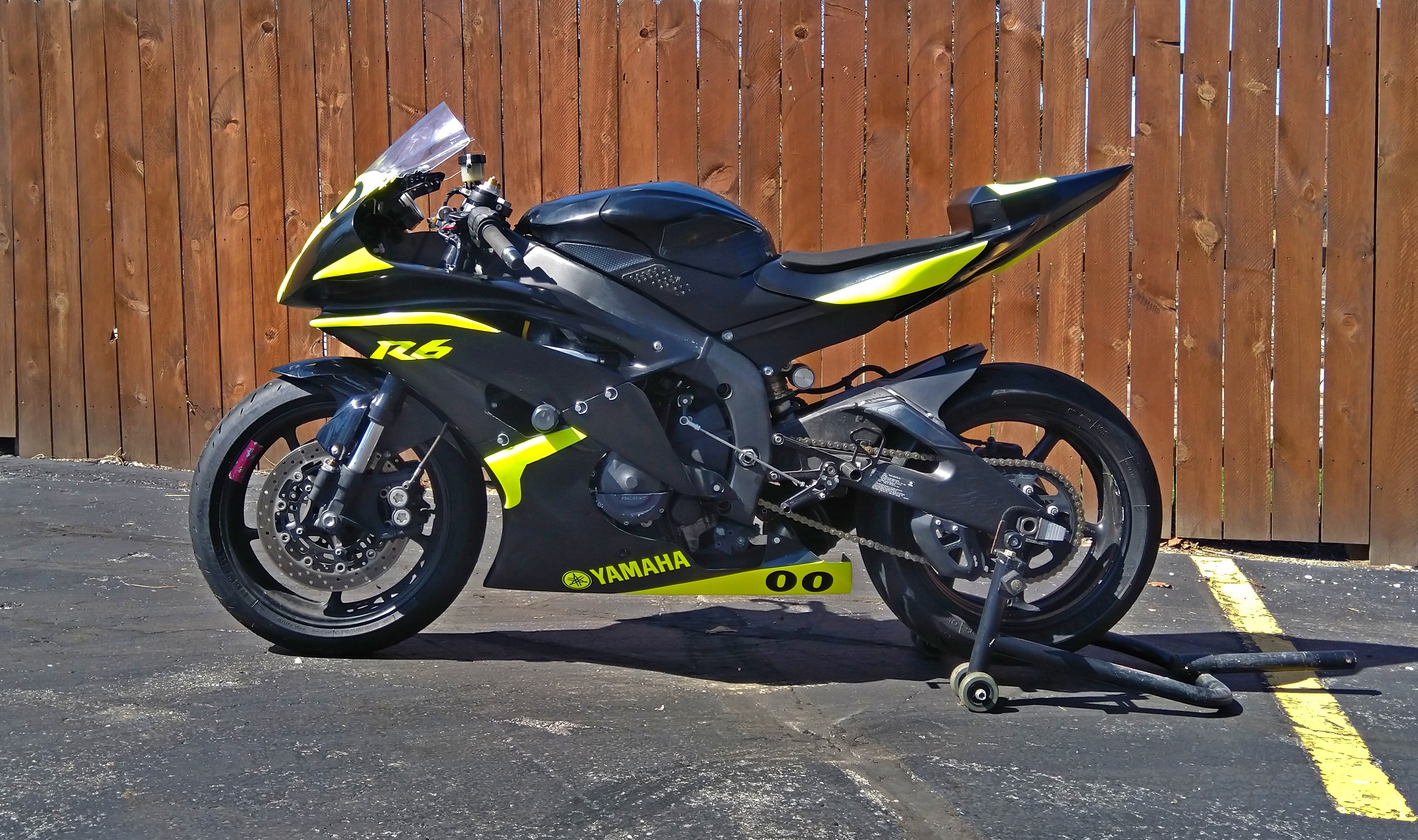
I have yet to take it for dynamometer tuning, but it’s on the to-do list. I am curious to see how close to stock hp/torque I am after this rebuild (hopefully above it with my full flow exhaust). I will post the tuning data in here when I get it done.
That’s it! This series is over. This project was fun and successful. If you want more information on a specific step that I haven’t included, please reach me via my contact form!