2012 Yamaha R6 Full Engine Rebuild: Part 3, Inspection & Cleaning
Recap: I rebuilt a 2012 R6 motor for a bike that I use as a track bike. Due to high mileage (>30k), poor low end performance, and compression much lower than spec, (as well as my “mechanical enthusiasm”) I decided to go ahead and do a full rebuild of the engine as well as a general cleanup of the chassis and cabling. This article is Part 3: Inspection & Cleaning, and deals with component acquisition, engine re-assembly, and finally startup and break-in.
This is one article in a series, which will detail the rebuild as well as offer guidance to any aspiring mechanics:
- Part 1, Introduction: Motivation, how to get started, and critical chemicals and tooling.
- Part 2, Disassembly: Some key parts of disassembly not well covered in the manual/other sources.
- Part 3, Inspection & Cleaning: Combustion chamber surfaces, valve and piston installation, valve clearance adjustment.
- Part 4, Reassembly: Some key parts of assembly not well covered in the manual/other sources. Starting it up and break-in period.
With this series of articles I aim to offer technical advice that is not well covered elsewhere, and concentrate it all in one resource. This series specifically focuses on the Yamaha R6, but will generally apply to any modern inline-4 supersport (600cc) or superbike (1000cc) motor (very similar construction between modern, fuel-injected, water-cooled aluminium racing engines).
1 Inspection
You can really go all out with making sure every critical surface is within the stated spec, but that may involve purchasing a large assortment of dedicated measurement tools. I think some application of common sense can drastically reduce the amount of “tolerancing” that must be done, and greatly reduce the cost and time involved here. I do generally recommend owning a micrometer set, where a full set that covers 0-6” will run you between $1-200. This will take care of most of the inspection, however a set of 0.1 mil precision calipers will probably work just fine on its own. For my critical surface measurement I focused on shaft journals, shaft lobes, piston skirts, valve faces and seats, stems, and valve runout. For the crank specifically, as I was replacing all of the bearings anyways, ensuring the shaft journals are within the stated space is sufficient. For the valve runout, I simply spun them on machining flats and watched the heads for wobbling. I also checked my connecting rods for true-ness on machining flats.
If you are doing a rebuild because of some particular concern, then you should focus measurements around that concern. For example, if there was some sort of piston damage or you found a bent connecting rod, I would then go and buy a bore gauge set and check out my cylinder completely. In this case, my cylinders were basically pristine and I didn’t bother measuring them at all. If there is some infinitesimal wear of the plating, the piston rings can make up the difference and still be in spec with a wider gap (do measure the piston ring gap upon reinstallation). Don’t ignore things that look funny! Measure them to make sure, but if it looks like new it probably is.
2 Cleaning
Being without a garage at this time, I did not want to clean my cases in my bathtub. I solicited the help of a local shop to have the cases, cylinder head, and oil cooler completely flushed and cleaned with solvents. I also asked them to seat the valves while they were at it. The manual advises against grinding compound, but a few turns of the valves using fine lapping compound to remove debris from the seats is quite fine and does not affect the seat or valve surface in any significant way. Remember that the valves are slamming into the aluminum head at up to 16,000 RPM, it’s not a fragile system. This cost an even $200 for probably 1h30m of work for them. and was worth it to avoid the mess and to have an extended chat with the head mechanic about what I was doing. They gave me great advice about re-assembly and general maintainance and operation. I would try to engage a local race shop if you can, as they have more specialized knowledge and are generally more willing to do custom “sub-work” as opposed to standard billing for a fixed maintainance item (nothing against dealership mechanics of course, I appreciate the economics it’s just not what I needed here).
I am going to comment a bit on cleaning metal surfaces. If it is something like hardened steel shaft journal/lobe surfaces you should not be doing anything remotely resembling sanding, this includes using scouring pads, etc. Anything that needs to be kept extremely smooth, such as journals or mating surfaces, should be cleaned with brake cleaner and a nylon brush or wiping cloth. For extremely stubborn surfaces it may be okay to use a rotary tool with a nylon or brass brush. I would advise against using a steel brush on aluminum surfaces as any significant pressure will result in significant material removal.
With the exception of the Ni-Si-C plated cylinders, there are no other stock components with special coatings. However, the aluminum and titanium components will have at least a passivating oxide layer, which may have been significantly extended if the part is subject to thermal cycling, such as on exhaust valves or pistons. Passivating oxides are oxides that form on metal surfaces and stabilize to some small depth. For aluminum and titanium these are stable at room temperature conditions at ~ 5 nm. The reason that these layers stabilize so quickly that these metals are so good at oxidizing that the bulk metal can’t pull oxygen from the surface metal after some initial oxygen intake. However, if you increase the temperature or otherwise affect the thermodynamics here, the oxide layer can extend into hundreds of nm or even a few um. Just a fun fact that is relevant in the next section.
2.1 Pistons
After 30,000 miles the pistons had quite the carbon buildup. I could have asked a shop to clean it off but I already own a 5.0 L 200 W ultrasonic cleaner and some beakers so I took responsibility for anything less than ~ 3-4” in diameter. I experimented with carburetor cleaner, acetone, and diluted Simple Green. As far as I understand, a brand new stock piston is cast aluminum, with machined skirts and pin surfaces, so the finish is a matte aluminum. As I was cleaning these I noticed a dull gray surface coating on them, which I think is just the native oxide that has extended a few um due to the high temperatures reached in the combustion chamber.
One thing to note is that sonication of soft metals should be done sparingly due to caviation damage. Cavitation is caused by fast moving fluids coming up off of surfaces and forming low pressure bubbles. When the bubbles collapse, they cause a shock front to form which concentrates pressure at the surface. For soft metals, this will leave little microcraters in the metal. In general, for short durations, this won’t leave the metal any rougher than if it was finely sandblasted, however extensive sonication can remove too much material. I did notice some fine black powder in the bottom of my acetone-filled beakers after cleaning, and this is probably a tiny bit of aluminum oxide from metal that was removed in this manner.
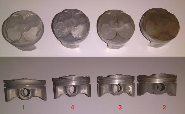
Here is what was done to each piston:
- 1:1 simple green to water, 60 C, 20 min sonication. This was excessive, and I’ve learned it’s wrong to use caustic chemicals on Al. It nuked the carbon off very nicely but caused a pocking/tarnishing on the Al surface.
- 2 x [sonication for 2 min + 58 min soak in 60 C chem-dip (#0996)].
- 2 x [sonication for 2 min + 58 min soak in 60 C acetone].
- Sonication for 20 min in 60 C chem-dip (#0996).
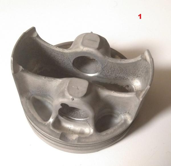
I left the oxide layer as intact as possible with the chemical treatments by visually checking the surface every 10 minutes. I noticed significant tarnishing of the piston cleaned by 1:1 Simple Green (process #1), due to my not understanding how alkaline of a solution that is (10:1 is probably better). This left a finish of noticeable roughness that I did not like, especially on the skirt and piston face. I used an Al-rated bristle disc to give it a smoother finish (Scotch-Brite Roloc Bristle Disc 07528). I mostly wanted to see how the bristle disc would work on the Al, and I think the piston would have been fine as shown in Figure 1. The main consideration is the ring grooves and the piston skirt surfaces and nominal diameter. If any of that is out of spec or damaged, replacing the piston is advisable. While the change in the surface finish is significant, the roloc disc did not remove any measurable thickness on the skirt or surface to 0.1 mil.
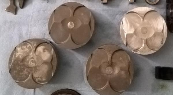
The next time I open the engine up I will replace the pistons with forged Al racing versions, so all these have to do is not explode for a year or two. They are all very smooth still, and while not as pristine as brand new OEM pistons, I expect they will stay clean for the next few seasons.
2.2 Crankcase
The cases were cleaned by a race shop that dipped them in their chem-dip vat and rinsed them off. I believe they manually removed any remaining material on the mating surfaces with just cloths and brake cleaner.
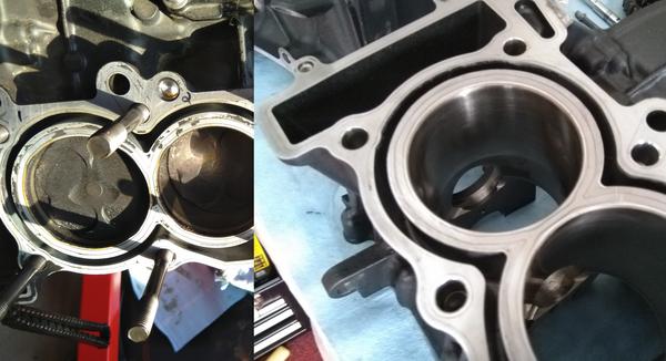
Here’s the bottom case with new crank bearings installed, so fresh!
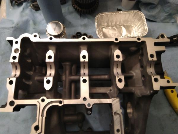
The main focus in cleaning the cases should be on all of the mating surfaces and oil channels, especially for the bearings. The rest of the cases were fairly clean as-is. If you are changing your oil on a regular basis you should not be seeing significant residue buildup in the crankcase.
2.3 Cylinder Head
The most important cleaning of all was that of the cylinder head. Carbon deposits were removed by soaking the head in chem-dip and manual cleaning with carburetor cleaner. The titanium valve surfaces were cleaned with a steel wire brush (not the valve seats on the head). The valves were gently seated with fine lapping compound, where the primary intent was to remove microscopic debris from the valve seat and not to grind them in any significant way. This is much nicer, to be sure:
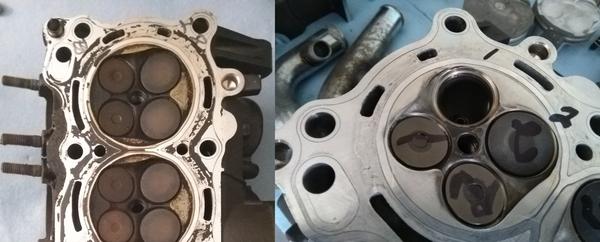
At this point I did the “bounce test” on all of my valves. I lubricated the valve stems with just engine oil and let them fall into the seats. If they spring back up that means they are making uniform and simultaneous contact with the seat which is what you want. I did also apply red layout fluid to the valves and check that they leave a uniform continuous ring on the seats. This also verifies that your valve guides are still true and do not need replacing. If there is any side-to-side play or irregular contact, it’s likely that that valve guide needs to be replaced. I imagine running out of spec valve guides is one of the easiest ways to cause damage to the cylinder head.
Ideally, you would replace the valves and get the seats re-cut to ensure a pristine mating surface. However, as I show in the reassembly section, the valves seal very well after this limited refurbishment. Eventually I will get this head ported and install race cams. At that time I will get the seats cut simultaneously (usually part of the porting job), and replace all of the valves with new ones.
3 Comments
Cleaning is never particularly fun, but in this case, it provides an opportunity to learn about solvent chemistry, and also the oxidizing chemistry of metal surfaces! Wow!!! Let’s finish this up and put the whole thing back together, over in the final section: reassembly.
