2012 Yamaha R6 Full Engine Rebuild: Part 2, Disassembly
Wow I really neglected the completion of this series! I did this rebuild over a year ago! One whole year! Anyways, here is the rest of it. Recap: I rebuilt a 2012 R6 motor for a bike that I use as a track bike. Due to high mileage (>30k), poor low end performance, and compression much lower than spec, (as well as my ďmechanical enthusiasmĒ) I decided to go ahead and do a full rebuild of the engine as well as a general cleanup of the chassis and cabling. This article is Part 2: Disassembly, and deals with engine removal and disassembly.
This is one article in a series, which will detail the rebuild as well as offer guidance to any aspiring mechanics:
- Part 1, Introduction: Motivation, how to get started, and critical chemicals and tooling.
- Part 2, Disassembly: Some key parts of disassembly not well covered in the manual/other sources.
- Part 3, Inspection & Cleaning: Combustion chamber surfaces, valve and piston installation, valve clearance adjustment.
- Part 4, Reassembly: Some key parts of assembly not well covered in the manual/other sources. Starting it up and break-in period.
With this series of articles I aim to offer technical advice that is not well covered elsewhere, and concentrate it all in one resource. This series specifically focuses on the Yamaha R6, but will generally apply to any modern inline-4 supersport (600cc) or superbike (1000cc) motor (very similar construction between modern, fuel-injected, water-cooled aluminium racing engines).
1 Organization
Keeping fasterners from a single sub-assembly together is a smart idea. You may have a more sophisticated sorting solution but I simply kept them together in ziploc bags and that worked very well. If hoses or cabling are, or seem to be, identical, you should label them. In terms of marking parts, paint markers or nail polish are a smart idea. If the material is not solvent resistant (paint or plastic), then colored zip-ties or low-tack tape + marker is suggested. The Yamaha R6 is a very well thought out machine. In general, motorcycles used in racing series have been engineered to be straightforward and fool-proof to assemble and re-assemble, due to the frequency at which that is done. I will finish this section with an attempt to make you feel good: it is very difficult to put this motorcycle back together the wrong way. Itís more likely that you forget to connect/assemble something altogether, rather than doing it in a wrong way (itís mostly impossible to do incorrectly without damage). Any actually identical parts usually come in sets of 4 (the number of cylinders), and you should aim to label them accordingly.
2 Engine Removal
The service manual has a dedicated section called Engine Removal (5-1 to 5-6 in the manual I have). Literally following that section in order and step by step will get you in a position where you can pull the engine out. I would add that I like to plastic/aluminum wrap or tape wrap a lot of the hoses/wires that will be sitting out after disconnection in order to keep off dirt. Also labelling things with generic connectors like your case grounds is helpful. Please do remove the radiator, especially if working alone. The added clearance helps to easily remove the engine out of the frame. When all fluids are drained and all hoses/wires are disconnected, you can start removing the engine mount bolts (two long rear mounting bolts and 4 forward shorter mounting bolts).
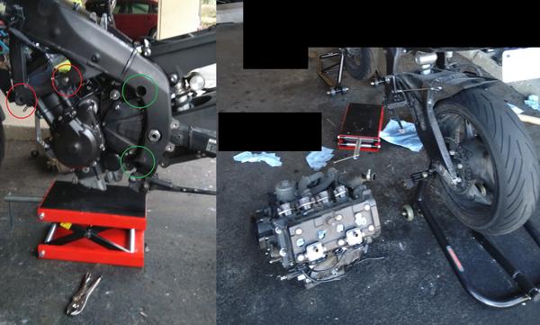
Having the bike up on stands or lifted via crane gives you more clearance to maneuver the engine out. I just used my regular track stands (pictured, above), and had plenty of space to work with. I slid my floor jack underneath and lifted it until it hit the oil pan and just started to hold the weight of the engine/bike. I then removed both sets of ďEngine mounting bolt (rear upper/lower side)Ē (green, Figure 1), and also one set of ďEngine mounting bolt (front side)Ē (red, Figure 1). I raised the jack slightly and let the engine tilt forward until it was relatively balanced on the jack, and then removed the remaining mount bolt while holding the the engine near the exhaust ports with my other hand. Carefully, I slid the engine forward first, to clear the swingarm and frame mount points, then I lowered the jack all the way down and slid the engine out sideways. Certainly using a crane for this would be easier, but this worked out well enough.
3 Engine Disassembly
Following the manual step-by-step and in-order is quite fine for full disassembly (reverse for reassembly). There are multiple steps that I skipped based on my goals. For example, I didnít plastigauge the camshaft journal/seat to check for clearance. The seats donít hold removable bearings like for the crankshaft, so the only option if they are out of spec is to replace the entire cylinder head. I measured the camshaft journal diameter and found it to be completely within spec. The seats didnít look particularly worn and I didnít really think twice about it. I skipped/ignored certain steps like this throughout the rebuild, and itís up to you on how far you want to go here.
There are many installed components that are under high static load, e.g. camshafts. Care must be taken to never concentrate excessive force on high-strength steel components or they will fracture. The service manual covers all of the critical situations well enough. Additionally, I highly recommend purchasnig the dedicated removal tools for the flywheel, the clutch basket, and a sheave holder for the flywheel so that you can remove the camshaft timing gear from the crankshaft safely (more tool info in Part 1, Introduction). Fracturing/damanging your crankshaft is not repairable, and a replacement crankshaft costs $5-600.
In general, low-cost bearings/seals, etc, should just be replaced de facto, as you are disassembling the engine anyways. More on this in Part 4, Reassembly. Here I will note some things that I did or that I think are important outside of the service manual content.
3.1 Cylinder Head
Come up with a scheme for labelling your valves/valve components. Youíll want to keep them together:
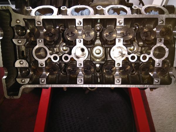
A magnetic pickup tool is nice here, as it lets you easily remove the shims/buckets. Also, a valve organizer tray is only ~ $10, and is 100 % worth it to keep your valve components sorted.
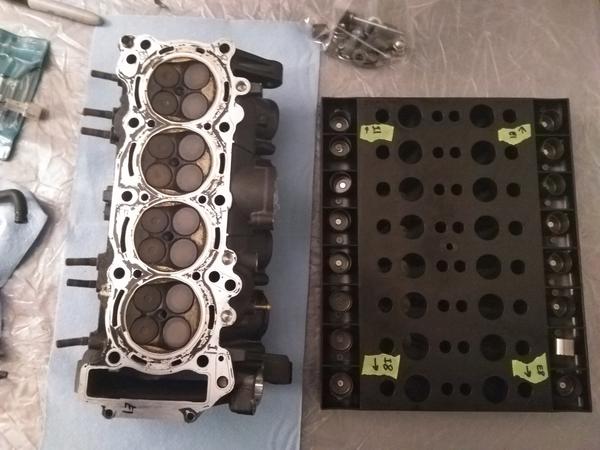
I mentioned that I had poor compression, and one thing we can do to diagnose the root cause is a leak test of the valves. For this, I set the head valve-side down on some sockets (be very careful to not dent/scratch the combustion cylinder surfaces or the mating surfaces), and poured water into the intake/exhaust ports:
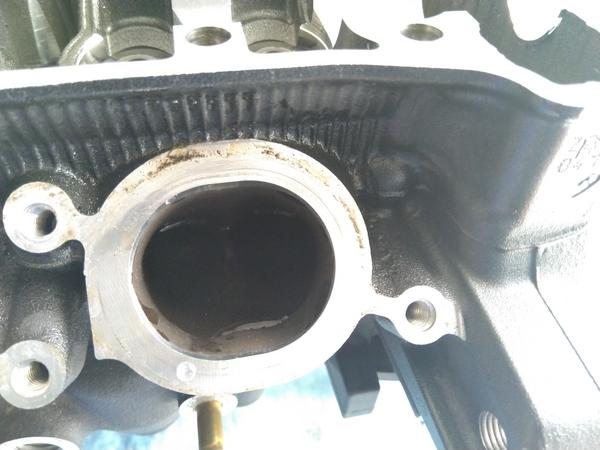
Almost immediately all valves started beading up, with around four of them just freely dropping water. This is a good indicator that the valves are not sealing well and affecting low rpm compression (at high rpm there is valve float anyways, and compression is more complicated and involves intake/exhaust vacuum), causing the poor low rpm power I had previously felt.
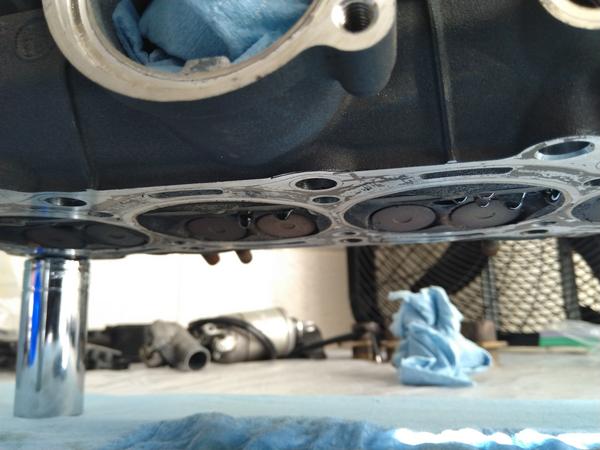
Indeed, after removing the valves, itís clear that some surfaces have carbon/particle buildup that is preventing full valve closure:
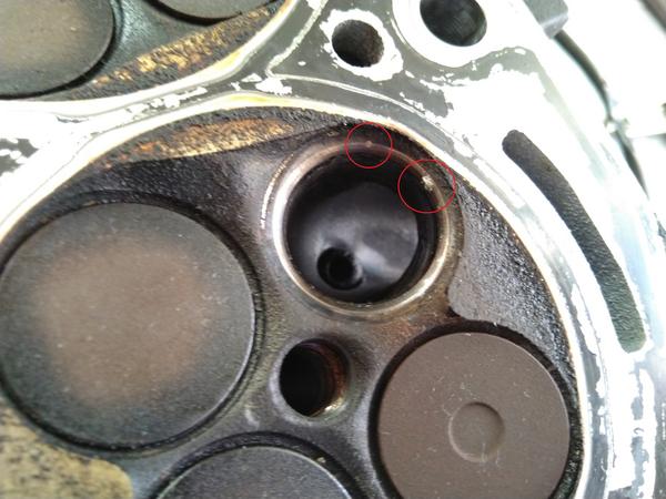
Top-end refurbishment is a common and critical maintainance item. Itís easy to see from the images above why poor valve conditions can drastically affect performance.
3.2 Crankcase
Similar to the valve sealing test, you can do the same thing with the cylinders to check the ring seal. Here I manually turned the crankshaft to set the all pistons at half-stroke and poured in water to the very top of the cylinder. These are the water levels after one hour:
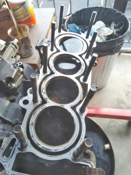
You can see the top two pistons have perfect sealing, and that the next two have progressively worse seals. It could be the case that piston ring seal in the bottom two was contributing to poor performance, but I would bet that it was almost 100 % due to the valve seal due to the uniformity in my compression numbers (all cylinders showed approximately the same reduced compression, to within 10 psi). It is a tribute to modern metallurgy that the piston rings seal almost perfectly when cold after 30,000 miles. In general, the bottom end is modern mechanical wizardry, and the crankshaft, axles and gears had pristine surfaces in general. By the way, check your oil pan when you pop it off:
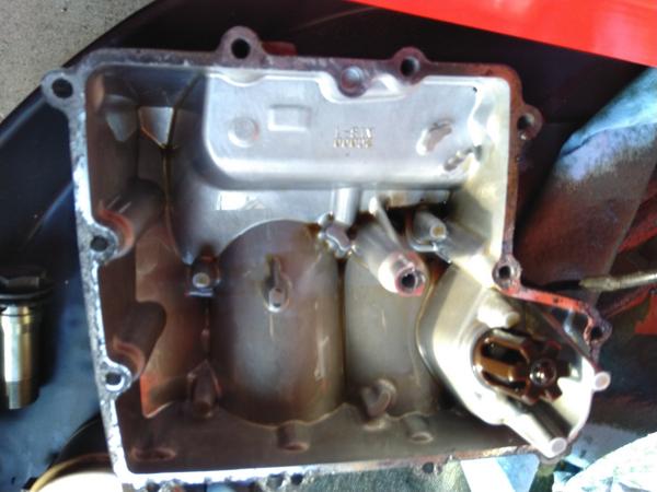
mine was squeaky clean, but if you notice any metal shavings or significant residue in there, it might indicate a more serious problem and require more detailed inspection.
Moving on, the clutch basket nut is torqued to 85 ft-lb, which is quite a lot. I used a PVC pipe on the basket clamping tool to get leverage to hold it in place for removal and reinstallation:
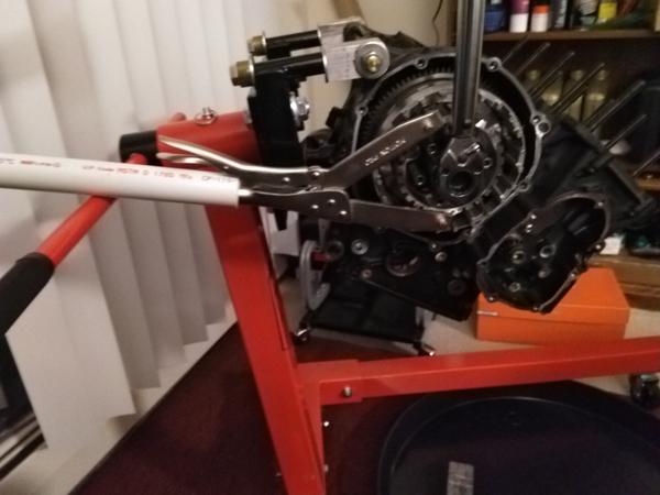
Crankcase separation is pretty straightforward. Remember to keep all cylinder-specific components together as they have worn in together. Also, do not mix up connecting rods, they have precisely calibrated journals and you need to buy the exact bearing for that particular crankshaft/connecting rod journal pairing. Take note of the factory calibrated diameters, for example on the crankshaft:
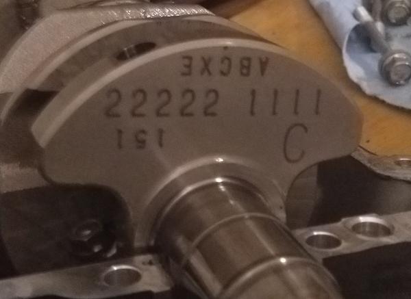
When removing the pistons, gently slide them out of the top while keeping them square and keep the connecting rod away from the cylinder wall. Scratching the cylinder wall is not easily repairable as it is an Ni-Si-C ceramic coating on the walls. You would have to send it in to get bored/re-plated ($$$). That being said, it is difficult to scratch barring the use of a large tool or some kind of equally-hard particle getting stuck between the ring and the cylinder wall. After a while you should get to the point where everything is separated from everything else (or close to):
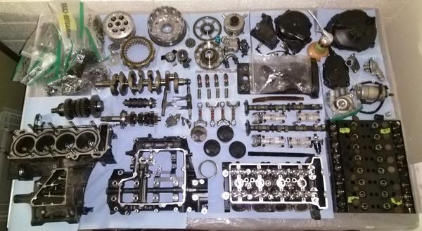
Good job! Note that I did not disassemble absolutely everything. For example the main/drive axles are held together by a bunch of circlips and have retainers that go in a particular orientation/order. I visually inspected the gears and saw no visible damage or significant wear. In this case, I didnít think it was worth my time to disassemble these and I simply cleaned mating surfaces that went into bearings/shift forks, etc.
4 Comments
Alright, the thing is completely apart, we did it (I did itÖ you may not have done it yet)! Where can we go from here? What is the meaning of life? Well, the next step is probably to inspect and clean everything. Anything remotely related to combustion will have significant carbon buildup, for example:
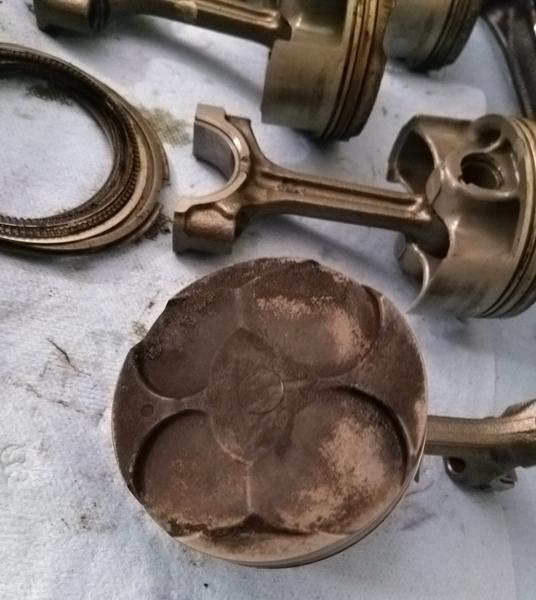
Weíll want to clean and replace certain things before reassembly, and that is the focus of Part 3, Inspection & Cleaning.
